Confusing emergency vehicle lighting can slow response times and increase road risks. When drivers do not quickly recognize warning signals, they may hesitate to yield. Understanding how these lighting systems work improves safety, compliance, and emergency access.
Emergency vehicle lighting works through coordinated LED modules, flash controllers, color-coded signals, and power management systems. Together, these components create highly visible warning patterns that alert drivers and pedestrians during urgent operations.
Read on to understand the key parts, operating modes, and legal standards behind emergency vehicle lighting systems.
Components of the Lighting System
1. LED Modules and Light Bars
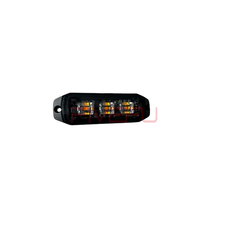
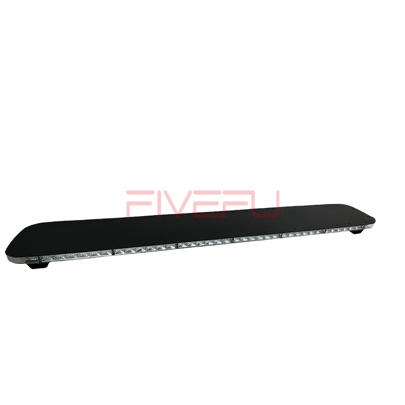
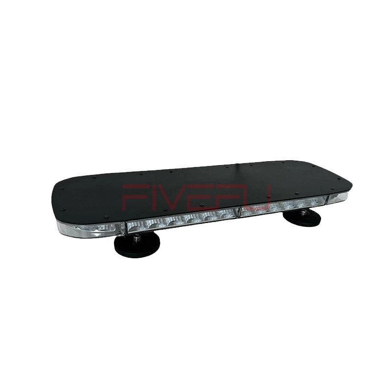
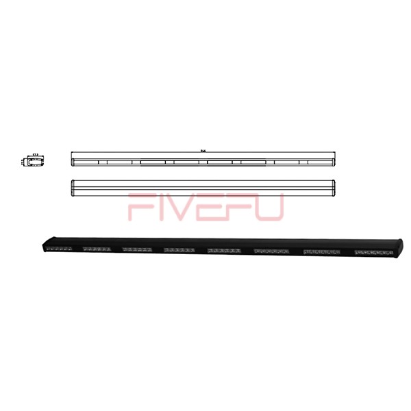
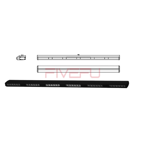
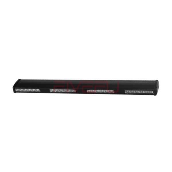
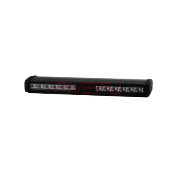
Modern emergency vehicles mainly use LED lighting instead of older incandescent or xenon strobe systems. LEDs are brighter, more durable, and more energy-efficient. They also respond instantly and support multiple programmed flash patterns. Roof-mounted light bars usually serve as the primary warning system, producing highly visible patterns such as wig-wag, quad flash, or alternating sequences.
2. Flash Controllers and Multiplexers
Flash controllers are the “brains” of the lighting system. They manage the timing, frequency, and sequence of each light output. Multiplex systems allow multiple lighting devices to communicate through a centralized control network, reducing wiring complexity and improving reliability. These controllers also help ensure that the lighting setup remains compliant with required regulations.
3. Wiring Harness and Power Distribution
Emergency lighting systems need dedicated wiring, fused circuits, and secure grounding points to handle high electrical demand safely. Wiring harnesses are designed with sealed connectors and protective routing to resist moisture, vibration, heat, and cold. Reliable power distribution is critical because any wiring failure can reduce visibility and compromise safety during emergency response.
4. Control Switches
Drivers or operators manage the lighting system through switches located on the dashboard or center console. These controls usually allow the vehicle to change between several operating modes, including:
-
Normal driving mode
-
Emergency or response mode
-
Scene lighting mode
This setup allows operators to match the lighting output to different situations without delay.
5. Power Management and Battery Backup
Some emergency vehicles include auxiliary batteries or backup power systems. These provide continued lighting operation if the main engine, alternator, or primary battery fails. This redundancy is especially important during roadside incidents, extended operations, or rescue scenes where visibility must be maintained at all times.
Color Codes and Standard Placement
| Zone | Color | Typical Use |
|---|---|---|
| Front | Red / Blue | Primary emergency warning |
| Rear | Red / Amber | Brake, warning, or hazard signaling |
| Side | Amber / Blue | Cross-traffic and intersection warning |
| Scene Area | White | Work area or interior illumination |
Regulatory guidelines such as FMVSS and SAE standards help define acceptable light color, placement, brightness, and performance. These standards are important because they make emergency vehicles more recognizable and help maintain public understanding of warning signals.
Summary
Emergency vehicle lighting combines LED modules, flash controllers, color coding, and backup power to deliver clear warning signals, improve visibility, and support legal compliance during urgent response situations.